Een tijdje geleden kwam ik een ontwerp van een ESR meter tegen. Ik heb toen besloten dit na te bouwen maar de uitlezing met een pic + lcd te maken.
Mijn schema:

Foto’s:
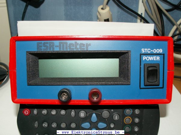
De tekst is er met wrijfletters opgezet.


jul 22 2008
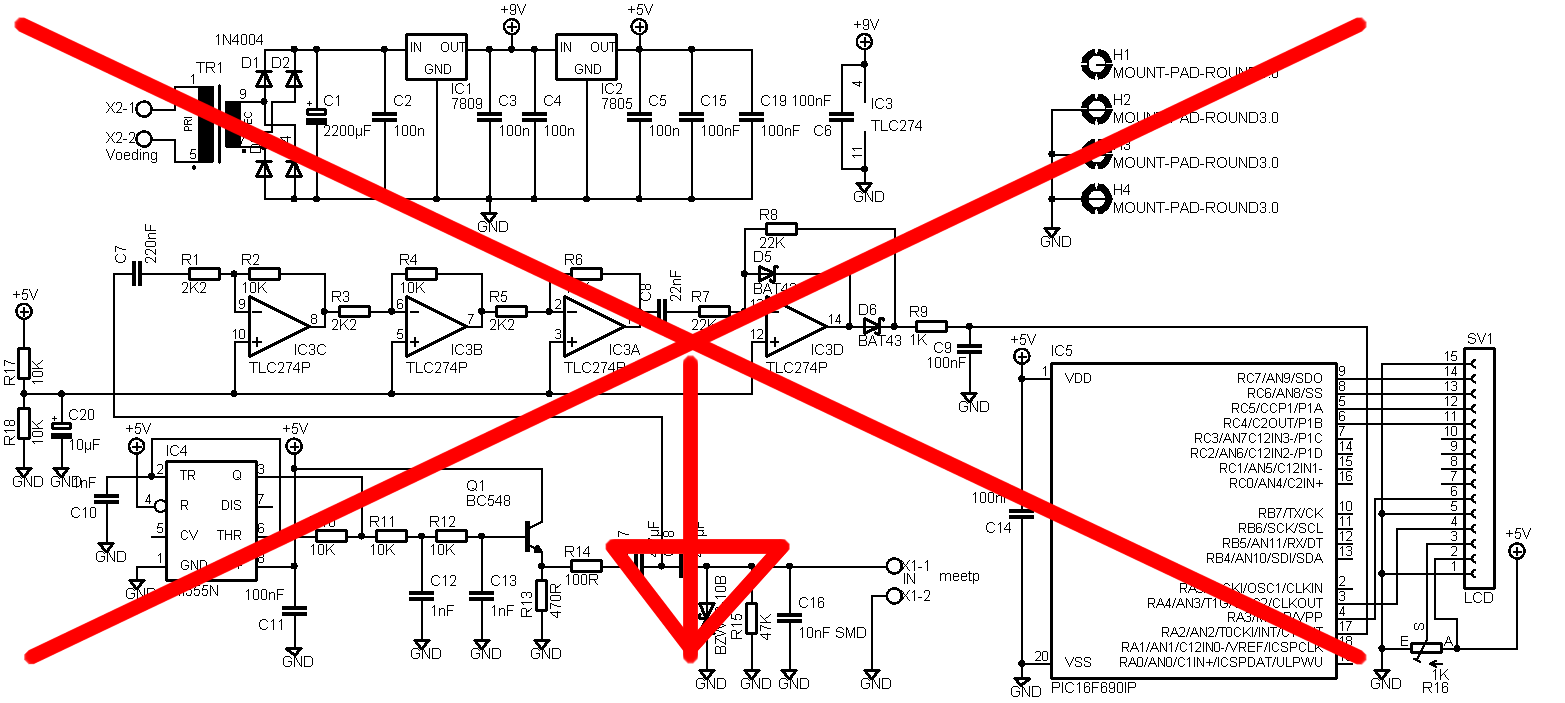
Ik had blijkbaar een fout in het schema gemaakt. De niet inverterende ingangen van de opamp moesten blijkbaar niet aan de massa verbonden worden maar aan 2,5V. Dat heb ik nu opgelost door het ic voetje op headers te solderen en daaraan een spanningsdeler te maken.


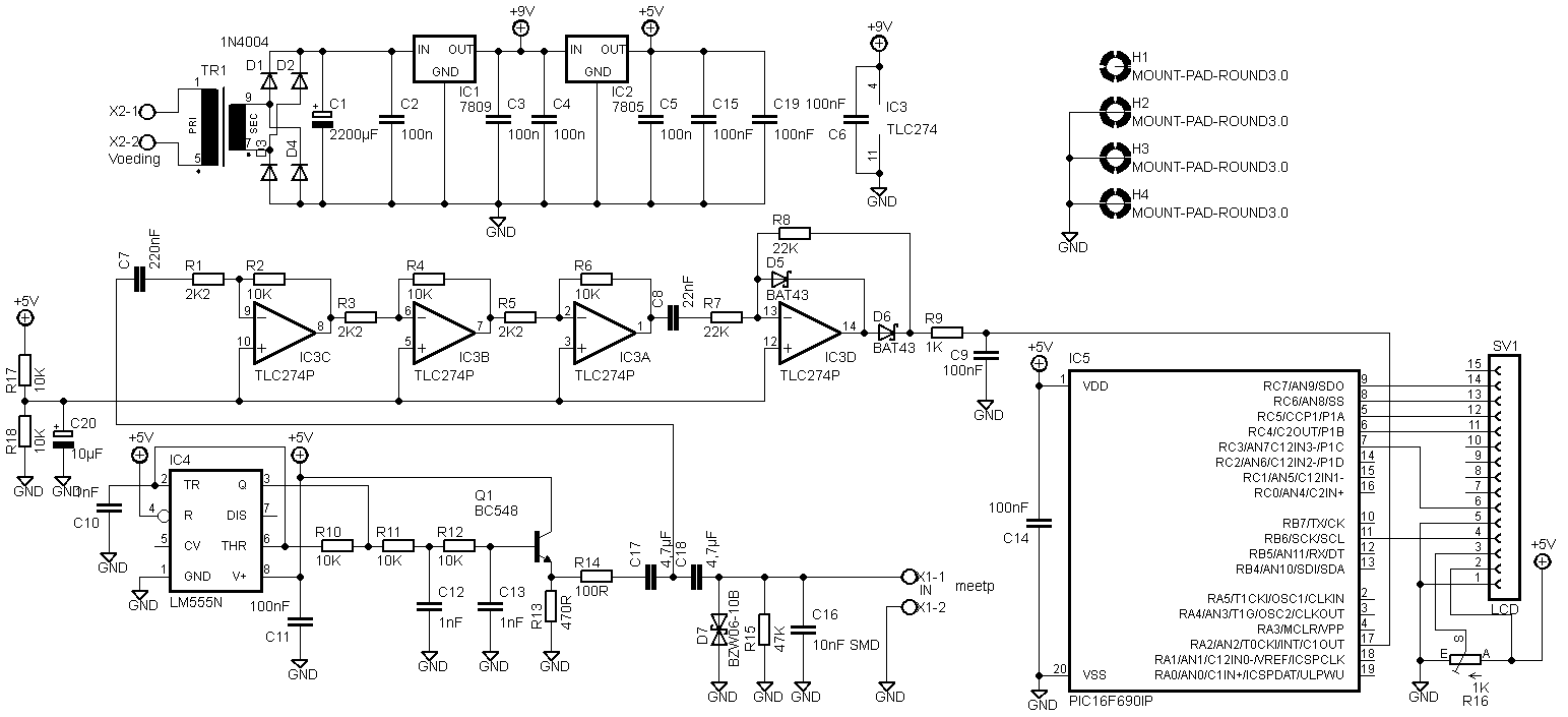
Nieuw schema:
feb 24 2009
Ik heb nu de code werkend gekregen. Er is iets mis met picbasic waardoor de AD omzetting problemen geeft bij een 16f690. Daarom heb ik zelf een stukje code geschreven voor het “handmatig” uit te lezen.
De code:
'****************************************************************
'* Name : ESR_meter *
'* Author : [Stynus] *
'* Notice : Copyright (c) 2008 [www.elektronicastynus.be] *
'* : All Rights Reserved *
'* Date : 24/02/2009 *
'* Version : 1.1 *
'****************************************************************
'Config
 Device 16F690
 Config INTRC_OSC_NOCLKOUT, WDT_OFF, PWRTE_OFF, MCLRE_OFF
 XTAL = 8
 OSCCON = %01110111

 Dim spanning As Word
 Dim esr As Float

 Declare LCD_DTPIN PORTC.4
 Declare LCD_ENPIN PORTC.3
 Declare LCD_RSPIN PORTB.6
 Declare LCD_LINES 2

 TRISA.2 = 1
 ADCON0 = %10000001
 ANSEL = %00000100
 ANSELH = %00000000

 ADIN_RES = 10
 ADIN_TAD = FRC
 ADIN_STIME = 500

 Symbol lcdTijd = 600
 Clear
 Cls
 Print At 1, 1, "ElektronicaStynu"
 Print At 2, 1, " ESR-Meter V1.2 "
 DelayMS lcdTijd
 Print At 1, 1, "lektronicaStynus"
 DelayMS lcdTijd
 Print At 1, 1, "ektronicaStynus."
 DelayMS lcdTijd
 Print At 1, 1, "ktronicaStynus.b"
 DelayMS lcdTijd
 Print At 1, 1, "tronicaStynus.be"
 DelayMS lcdTijd

 Cls
 Print At 1, 1, " ESR-Meter V1.2 "
 Print At 2, 1, " ESR = , "
 Print At 2, 16, $FE,$40,$00,$0E,$11,$11,$11,$0A,$1B,$00


While 1 = 1
 GoSub AD_in
 spanning = spanning - 480
 esr = spanning / 19
 If esr > 27 Then
 Print At 2, 9, "Open "
 Else
 Print At 2, 9, DEC2 esr , " "
 EndIf
 DelayMS 550

Wend
AD_in:
 ADCON0 = %10001001
 DelayMS 510
 ADCON0.1 = 1
 While ADCON0.1 = 1 : Wend
 spanning = 0
 spanning.HighByte = ADRESH
 spanning.LowByte = ADRESL

Return
End
mrt 26 2011
Er is nog een aanpassing aan de print gebeurd die hierboven niet in het schema stond.

Het LCD moest namelijk anders worden aangesloten. Waarom ik dat verandert heb na de ontwerp fase weet ik ook niet meer, maar hierbij het aangepaste schema:
feb 27 2012
Ik heb Eagle bestanden gekregen van Predrag Mihajlovic met de correcte print layout. Deze kunnen hier gedownload worden: Link.
Hello,
I did 2 versions. First is one based on your schematics, except that I’ve changed those smd capacitors for standard through hole ones. Second one is somewhat modified. I’ve excluded transformer and put in standard dc jack. Also, pic and display header are located so far away from other stuff so that there is enough place for display to be on the pcb. Also, you’ll see that, on both versions I’ve also put pads for 27 and 22mm capacitors (4.7uF). Check it out and feel free to make any modifications you think are necessary. You can put it on your website if you like, maybe someone will find it useful 🙂
Peca.